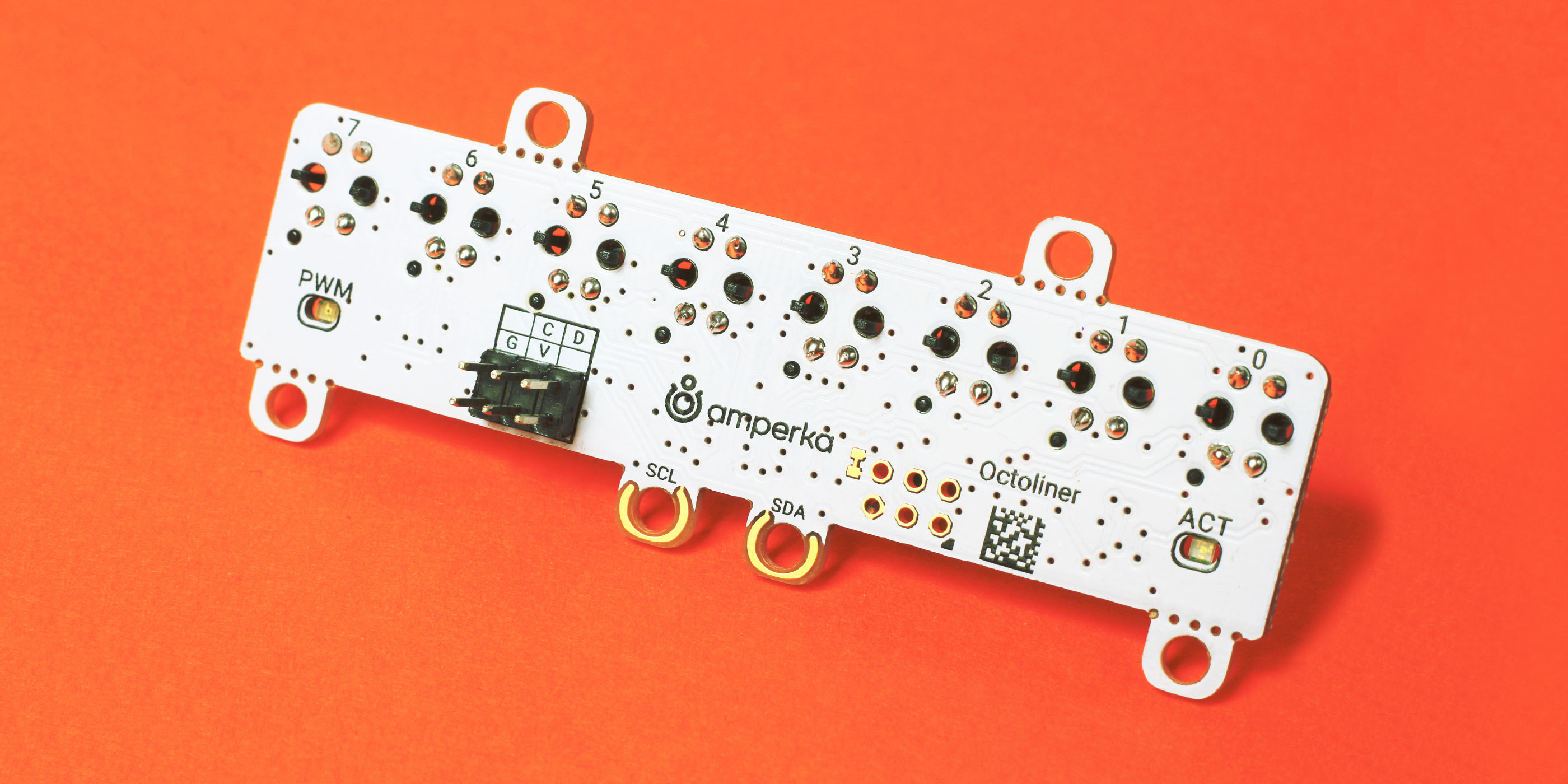
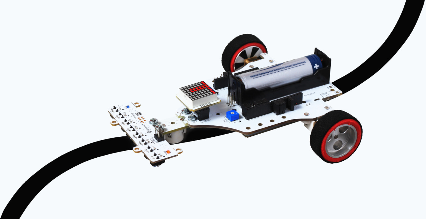
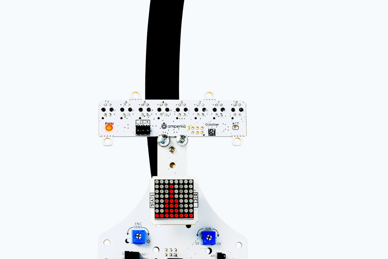
Octoliner
A smart sensor for your line follower.Ideal for hobbyists and STEM applications.


How it works
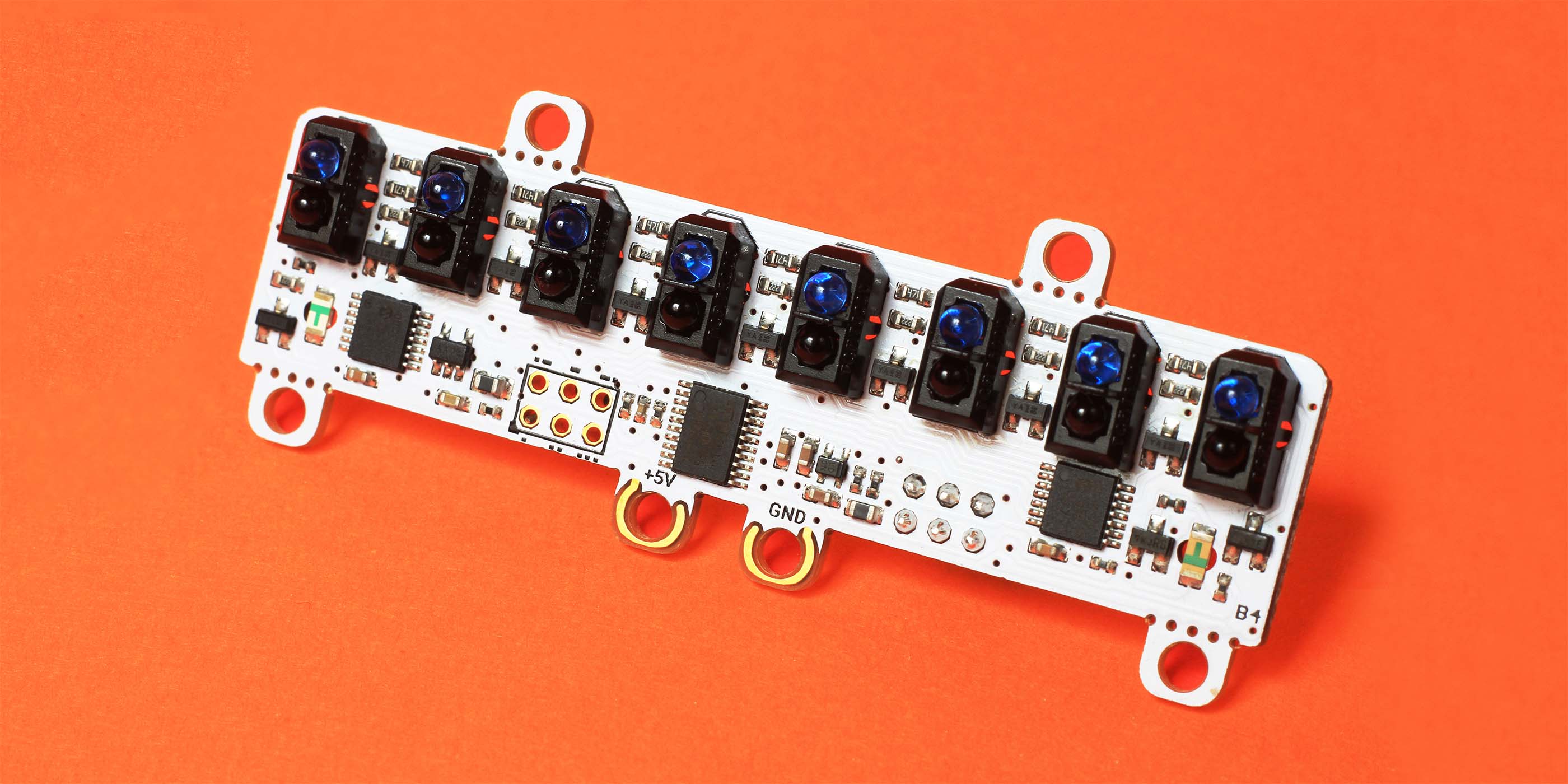
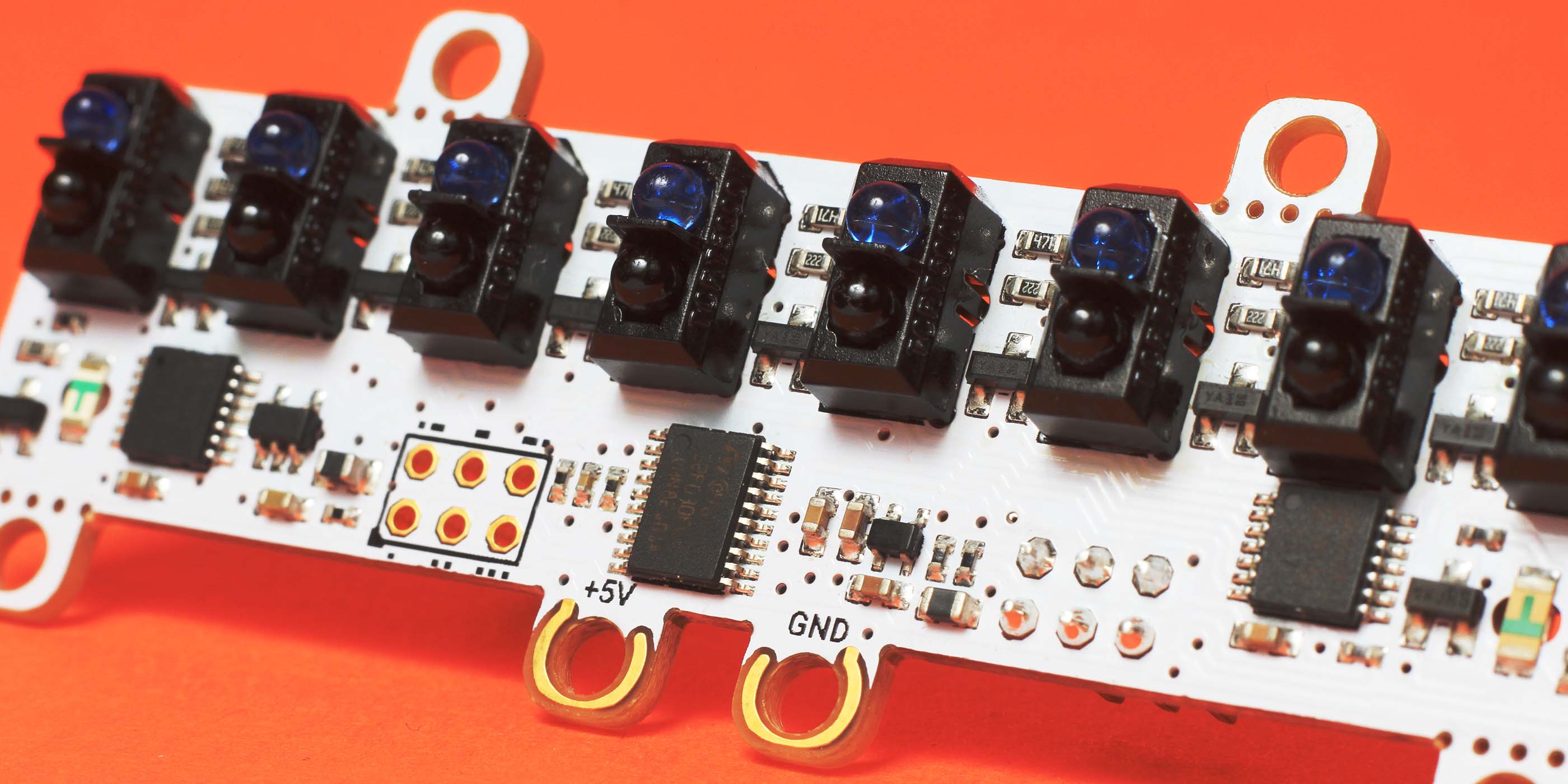
To understand whether the surface below the sensor is black or white a pair of optical elements (known as optocouple ) with an opaque blind between them is used. One of them is a LED which emits light. The light reflects back from the surface. The second element—which is a phototransistor—measures the amount of light it receives. Black, white, gray surfaces reflect back a different amount of light, so if we always emit at a constant brightness, we can understand the shade of gray by the amount of light returned back.
The optocouple works in the infrared spectrum, so a human eye can’t see the light. Nevertheless, objects react to the IR-light in the same way as to the human-visible light.
Octoliner hosts 8 such optocouples along with own microcontroller which provides powerful features described below.

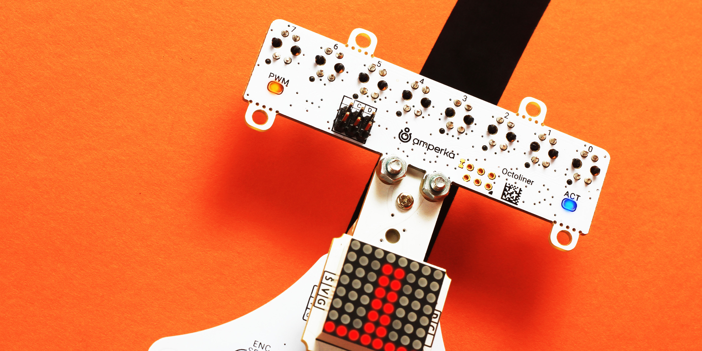
8 channels for full coverage
Analog & Digital modes
The line is either under sensor or not, right? Wrong! A sensing element can be positioned over the edge of the line. And this is a very valuable information. Instead of strict 0 or 1 you can understand the line is 1⁄2, 1⁄3, 1⁄4 under the cell. Unfortunately, it would require one analog pin per cell. Even rich controller boards can be unable to provide so many spare ADC pins. So, the majority of primitive sensors are binary: they round the intermediate values to either a 0 or 1, effectively throwing away useful data. Octoliner, thanks to the own microcontroller, is able to provide data from all 8 channels as is, without abusing your controller board.
If your algorithm expects binary data, no problems, Octoliner can as a digital sensor array too. You may configure the threshold of rounding programmatically.
Software-adjustable sensitivity for ambient lightness compensation
Even if your robot got to following line acceptably now, things can break in the evening. Are you preparing for a competition? The robot can go out of the track on the race lap. So disappointing. The reason is changing light conditions. Do you remember, the sensing elements work with light. They are affected by the sunlight too.
To solve the problem many sensor boards provide a small trimmer potentiometer which sets the threshold. Now imagine adjusting 8 of them with a screwdriver every time the environment changes. Total nightmare.
Octoliner overcomes the problem by allowing sensitivity adjustment from software. For all 8 channels at once. Furthermore, you can read ambient light level with a simple sensor and use this value to react accordingly. Continuously and automatically.
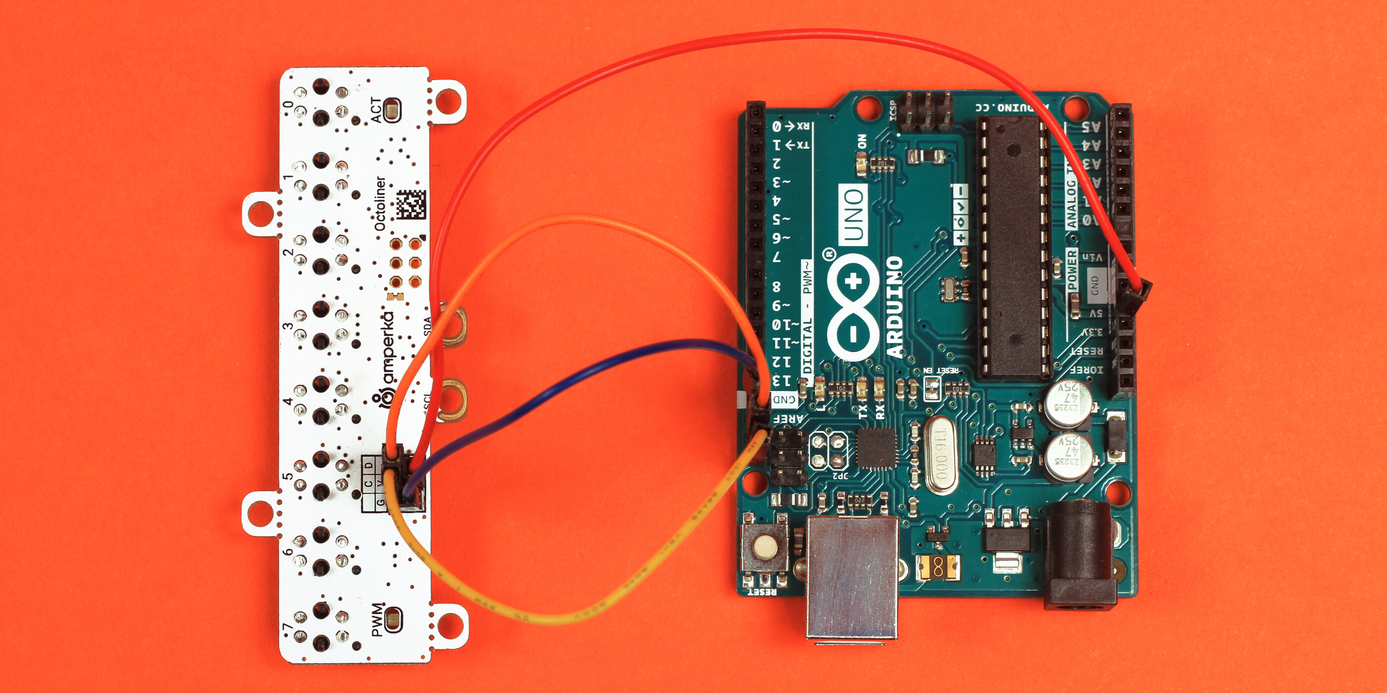
I²C interface: only 2 signal wires to control everything
With Octoliner you don’t talk to the sensor cells directly, instead you talk to the embedded microcontroller. The communication to read the data and to adjust the coefficients is done via I2C bus (also known as IIC or TWI). This means the sensor only requires two signal lines named SDA and SCL. Other I2C devices may co-exist on the same bus.

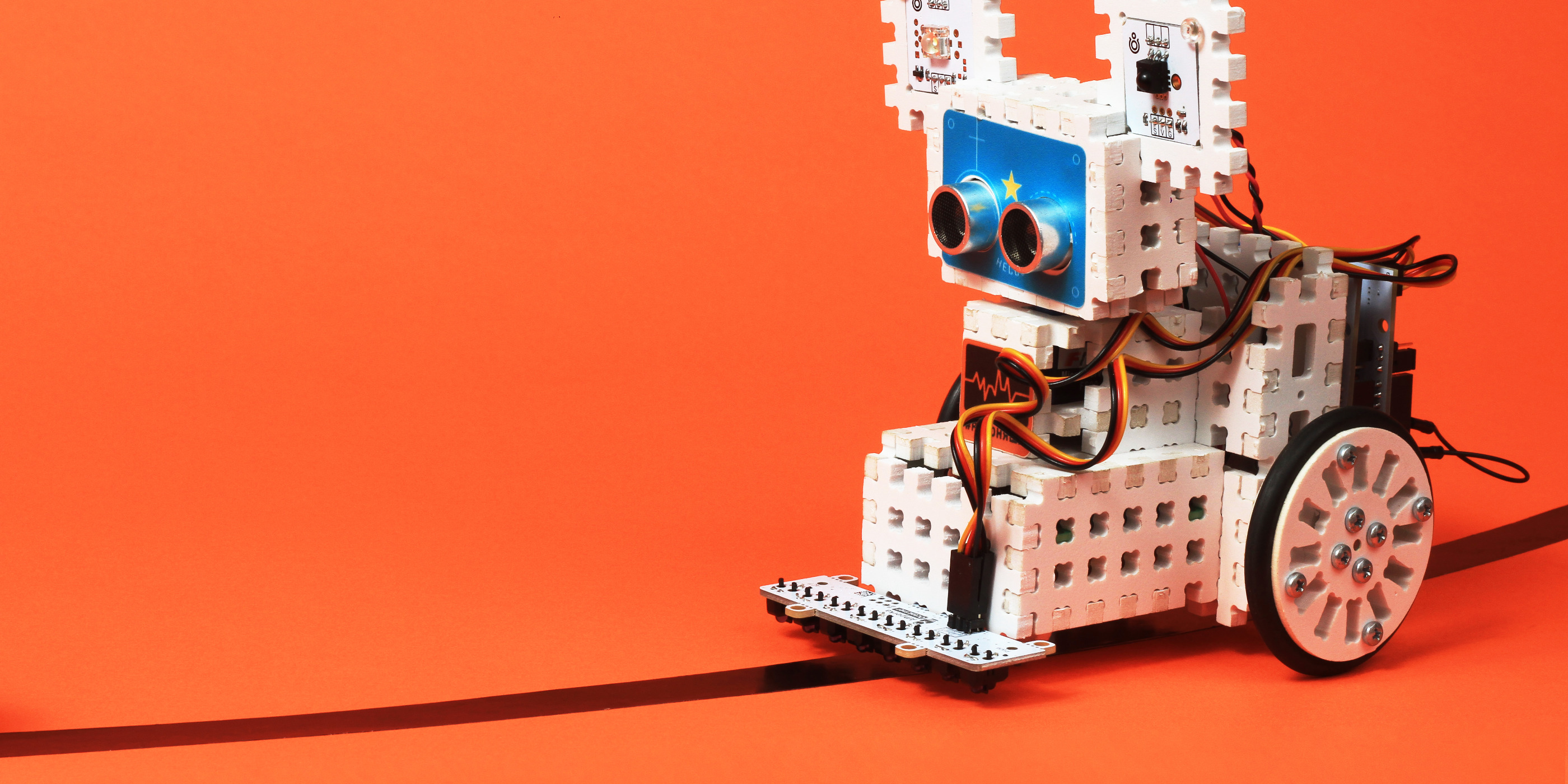
Octoliner is compatible to (but not limited to) Arduino Uno, Nano, Mega 2560, Pro Mini, and their analogs. It only requires the I2C bus and works with any voltage between 3.3 and 5 volts. So in fact compatible with the vast majority of DIY-controllers on the market.
We prepared a ready-to-use library for Arduino with quickstart examples.
Here’s a sneak peak:

// Include two libraries required to work with the module
// <https://github.com/amperka/Octoliner>
#include <Wire.h>
#include <Octoliner.h>
// Sensor on the standard bus and address
Octoliner octoliner;
void setup() {
Serial.begin(115200);
octoliner.begin();
// Set sensitivity to 200 of 255
octoliner.setSensitivity(200);
}
void loop() {
// Every 0.5 seconds...
delay(500);
// ...scan all 8 channels and output
// the values to Serial Monitor
for (int i = 0; i < 8; i++) {
Serial.print(octoliner.analogRead(i));
Serial.print(" "); // separate with TABs
}
Serial.println(); // line feed at the end
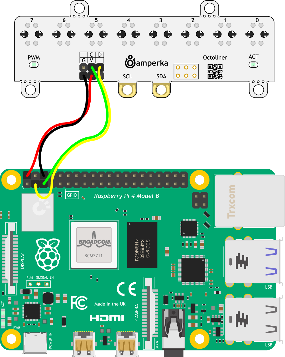
}Octoliner works fine with Raspberry Pi. For it, we have a Python library. Find it along with documentation and documentation on GitHub.
Here’s how it feels:
import time
# Import the class required from the `octoliner` library
# <https://github.com/amperka/OctolinerPi>
from octoliner import Octoliner
# Sensor on the standard bus and address
octoliner = Octoliner()
# Set sensitivity to 80%
octoliner.set_sensitivity(0.8)
while True:
# Read all channel values
values = [octoliner.analog_read(i) for i in range(8)]
# Print them to console
print(values)
# Repeat forever, twice per second
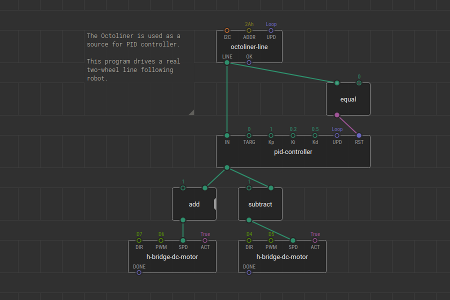
time.sleep(0.5)XOD visual programming language supports Octoliner as well. For this, we have published a library which provides a few nodes to interface with Octoliner. Among them, one outputs the final line position whereas another provides optocouple raw values for further processing.
Here’s how a line follower program looks like:

RoHS compliant
Octoliner does not contain lead, so it is safe for children. It also won’t poison the rivers one day it would be wasted.

Specifications
- Electrical Characteristics
- Rated Voltage: 3.3–5 V
- Supply Current (@5V): 87 mA
- Communication
- Interface: I²C
- Default Address: 42 ( 2A hex)
- Sampling Frequency (full 8-ch readout): 190 Hz
- Design
- Microcontroller: STM32F030F4P6
- Optocouples: TCRT5000
- Opamps: MCP6004
- Connection Options
- 0.1” pin headers
- Plated screw holes
- Mechanical Characteristics
- Dimensions: 80 × 30 × 16 mm
- Weight: 9 g